Lab 1.5 – Build a BIG-IP Cluster
In this lab we will build a active-standby cluster between BIG-IP-A and BIG-IP-B. As mentioned previously, to save time, BIG-IP-B already has already been licensed and had its device level settings configured. This lab will walk you through creating the cluster step by step. As you will see complex operation such as this start to become less effective using the Imperative model of automation. Clustering is one of the ‘transition’ points for most customers to move into the Declarative model (if not already done) due to the need to abstract device/vendor level specifics from Automation consumers.
The high-level procedure required to create the cluster is:
- Rename the CMI ‘Self’ Device name to match the hostname of the Device
- Set BIG-IP-A & BIG-IP-B CMI Parameters (Config Sync IP, Failover IPs, Mirroring IP)
- Add BIG-IP-B as a trusted peer on BIG-IP-A
- Check the device_trust_group Sync Group Status
- Create a sync-failover Device Group
- Check the status of the created Device Group
- Perform initial sync of the Device Group
- Check status (again)
- Change the Traffic Group to use HA Order failover (not required but shown as an example)
- Create Floating Self IPs
Task 1 – Rename objects and Setup CMI Global Parameters
In this task we will complete Items 1&2 from the list high-level procedure at the beginning of the lab. One of the idiosyncrasies of BIG-IP is that when you use the GUI Setup Wizard to set the hostname of the device, the wizard automatically renames the CMI ‘Self’ device to match the hostname. Since we configured the hostname via a REST call earlier this action did not take place.
Perform the following steps to rename the CMI ‘Self’ device:
- Expand the “Lab 1.5 – Build a Cluster” folder in the Postman collection
- Click the “Step 1: Rename the CMI Self Device’ item in the collection
- Examine the URI and JSON body. We are sending a POST request to
execute the equivalent of a tmsh
mvcommand to rename the existing object to the/mgmt/tm/cm/deviceCollection. Thenameattribute specifies the current name of the object (the factory default name), while thetargetattribute specifies the new name of the object. - Click the ‘Send’ button to rename the Resource.
- Change the request type from a POST to a GET and click ‘Send’. Examine the response to make sure the name was changed successfully.
Perform the following steps to set CMI Device Parameters
Click the “Step 2: Set BIGIP-A CMI Device Parameters” item in the collection. Examine the operation (PATCH), URI and JSON body. We will PATCH the newly renamed object (from the previous step) and assign the Config Sync IP, Unicast Failover Address/Port and Mirroring IPs:

Click the ‘Send’ button and examine the response to ensure the settings were changed
Click the “Step 3: Set BIGIP-B CMI Device Parameters” item in the collection. Examine the operation (PATCH), URI and JSON body. We will PATCH the newly renamed object (from the previous step) and assign the Config Sync IP, Unicast Failover Address/Port and Mirroring IPs.
EXTRA CREDIT: How is authentication to BIG-IP-B working if we never got an authentication token? (Hint: we cheated)
Click the ‘Send’ button and examine the response to ensure the settings were changed
Task 2 – Add BIG-IP-B as a Trusted Peer
The CMI subsystem relies on a PKI based device trust model to establish relationships between BIG-IP systems. In this task we will add BIG-IP-B as a trusted peer of BIG-IP-A. Establishing a trust relationship is automatically a bi-directional operation. As a result, when we establish the trust relationship, BIG-IP-B will automatically establish a trust relationship with BIG-IP-A. This task corresponds to items 3&4 in the high-level procedure.
Perform the following steps to complete this task:
- Click the “Step 4: Add BIGIP-B Device to CMI Trust on BIGIP-A” item in the collection
- Examine the operation (POST), URI and JSON body. We are using a special REST worker to add the device to the CMI trust. Additionally the JSON body must be specified in a very specific manner to ensure this step completes successfully. To minimize the chance for error the values have been completed for you already. You should, however, review and understand this step fully before continuing.
- Click the ‘Send’ button. The response for this request does NOT indicate success, only that the command is running.
- To check for success we have to check the status of the Sync Group named “device_trust_group”. To do this click the “Step 5: Check Sync Group Status” item in the collection. This request will GET the sync status for all sync groups on the system
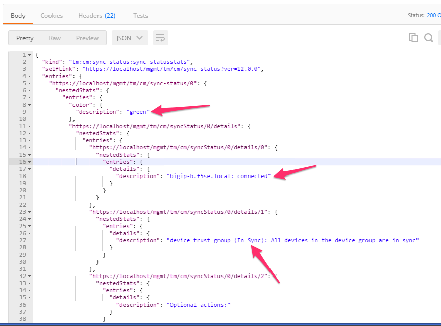
- Click the ‘Send’ button and examine the response. The should
indicate a color of ‘green’, that bigip-b.f5se.local is connected
and ‘In Sync’ (please notify an instructor of any issue):
Task 3 – Create a sync-failover Device Group
This task will create a Device Group object that will contain the two BIG-IP systems. The type of device-group will be a ‘sync-failover’ group, however, ‘sync-only’ groups can also be created with the same procedure but different attribute values. This task corresponds to items 5-8 in the high-level procedure.
Perform the following steps to complete this task
- Click the “Step 6: Create Device Group” item in the collection.
Examine the request type, URL and JSON body. We will POST to the
‘/mgmt/tm/cm/device-group’ collection and create a new Resource
called DeviceGroup1 that includes both BIG-IP devices and is set to
‘sync-failover’ type. We are also setting the device-group to
‘autosync’ so manual syncing is not required when configuration
changes occur:

- Click the ‘Send’ button and examine the response.
- To check the status of the device-group we have to check the status
of the underlying sync group on the system. Click the ‘Step 7:
Check Sync Group Status’ item in the collection and click ‘Send’.
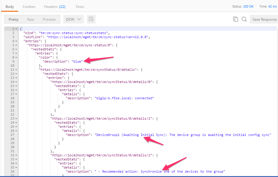
Examine the response and take note that the system is ‘Awaiting
Initial Sync’:
- We will now manually sync DeviceGroup1 to fulfill the need for the
Initial Sync. Click the ‘Step 8: Manually Sync DeviceGroup1’ item
in the collection. Examine the request type, URL and JSON body. We
will POST the the ‘/mgmt/tm/cm/config-sync’ worker and tell it to
‘run’ a config-sync of BIG-IP-A ‘to-group’ DeviceGroup1:

- Click ‘Send’ to initiate the sync
- Click the ‘Step 9: Check Sync Group Status’ item in the collection and click the ‘Send’ button. Examine the response to make sure that DeviceGroup1 is ‘In Sync’. You may have to click ‘Send’ multiple times as the sync operation can take a while to complete.
Task 4 – Perform Additional Operations
The remainder of the steps show how to manipulate various common items related to the HA config. In this task we will change the Traffic Group to use the ‘HA Order’ failover method. We will then initiate a failover and show how to view the status of the traffic-group.
Perform the following steps to complete this task:
- Click the “Step 10: Get Traffic Group Properties” item in the collection. Examine the URL, we will GET the attributes of the ‘traffic-group-1’ resource from the traffic-group collection. Click the ‘Send’ button and review the response.
- Click the “Step 11: Change Traffic Group to use HA Order” item in the collection. Examine the request type, URL and JSON body. We will PATCH the existing resource and specify an ‘haOrder’ attribute to change the traffic-group behavior.
- Click the ‘Send’ button and examine the response to verify the change was successful.
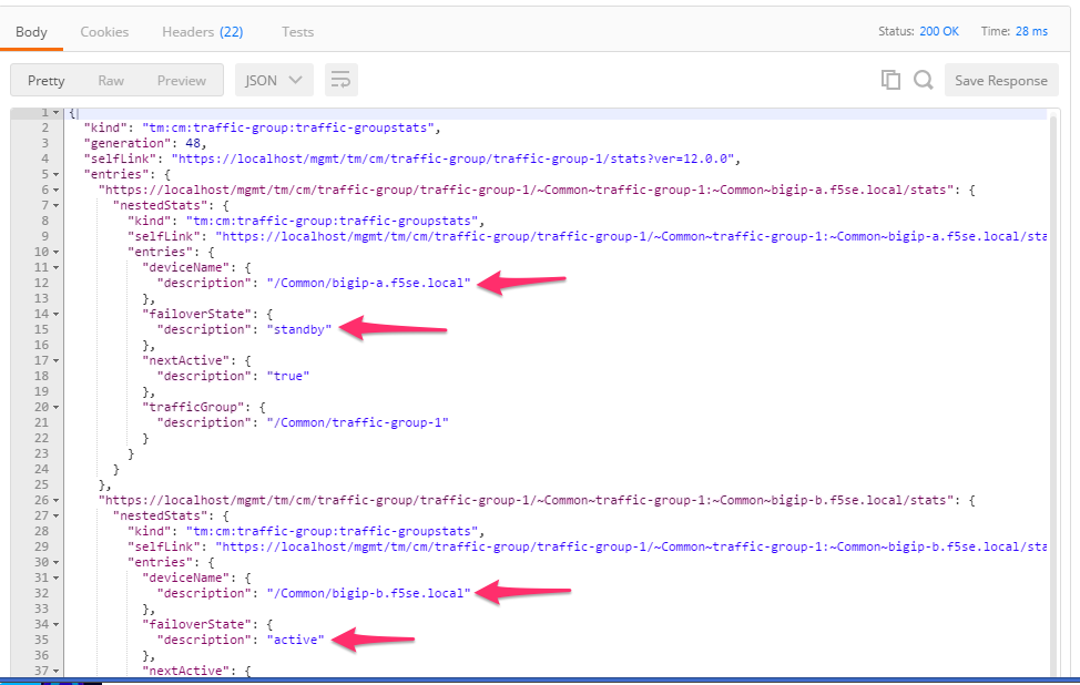
- Click the “Step 12: Get Traffic Group Failover States” item in the
collection and click the ‘Send’ button. Examine the response and
determine which device is ‘active’ for the traffic-group:
- Click EITHER the “Step 13A” or “Step 13B” item in the collection depending on which device is ACTIVE for the traffic group. Notice that we are sending the request to the ACTIVE device for the traffic group. Examine the JSON body and click the ‘Send’ button.
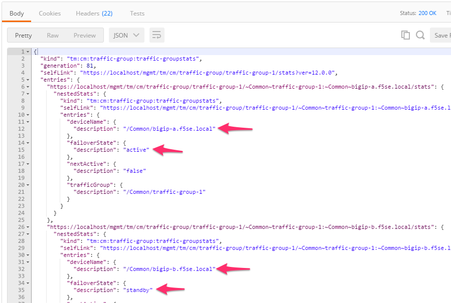
- Click the “Step 14: Get Traffic Group Failover States” item in the
collection and click the ‘Send’ button. Examine the response to
determine that the failover occurred properly:
Task 5 – Create Floating Self IPs
To complete the HA config we will now create a Floating Self IP on the Internal VLAN.
Perform the following steps to complete this task:
- Click the “Step 15: Create a Floating Self IP” item in the
collection. Examine the request type, URL and JSON body. We will
create a new resource in the
/mgmt/tm/net/selfcollection named ‘Self-Internal-Floating’ and an IP address of 10.1.10.3. - Click the ‘Send’ button and examine the response
- Click the “Step 16: Get Self IPs” item in the collection and click ‘Send’. Examine the response and verify the Self IP was created.